Reliable power electronics depend on more than selecting a high-rated module. They require disciplined coordination between the power stage, sensors, firmware, communication interfaces, and protection circuits. A module may pass a bench test, yet fail after cable length, switching frequency, or ambient temperature changes.
This guide presents five practical tips to Enhance compatibility between power modules and control systems. It examines voltage thresholds, startup timing, grounding, electromagnetic interference, and communication protocols. Small details matter. A 200-millisecond delay can trigger a false fault. A poorly routed signal wire can introduce visible noise into an analog feedback loop. A loose shield connection may remain unnoticed until the system enters a metal enclosure.
Field testing repeatedly shows that compatibility is a system-level responsibility. Engineers should compare datasheets, verify interface limits, and measure real waveforms with suitable instruments. Oscilloscope captures often reveal overshoot that software logs never record. Thermal measurements can also expose gradual drift near the module’s rated limit.
Not every design begins perfectly. A previous assumption about common ground may prove wrong. That is useful evidence, not failure. Careful reviews, controlled tests, and documented changes create more reliable results. The following recommendations aim to reduce integration surprises and support stable operation across production conditions. They also encourage engineers to question convenient shortcuts before those shortcuts become expensive field problems.
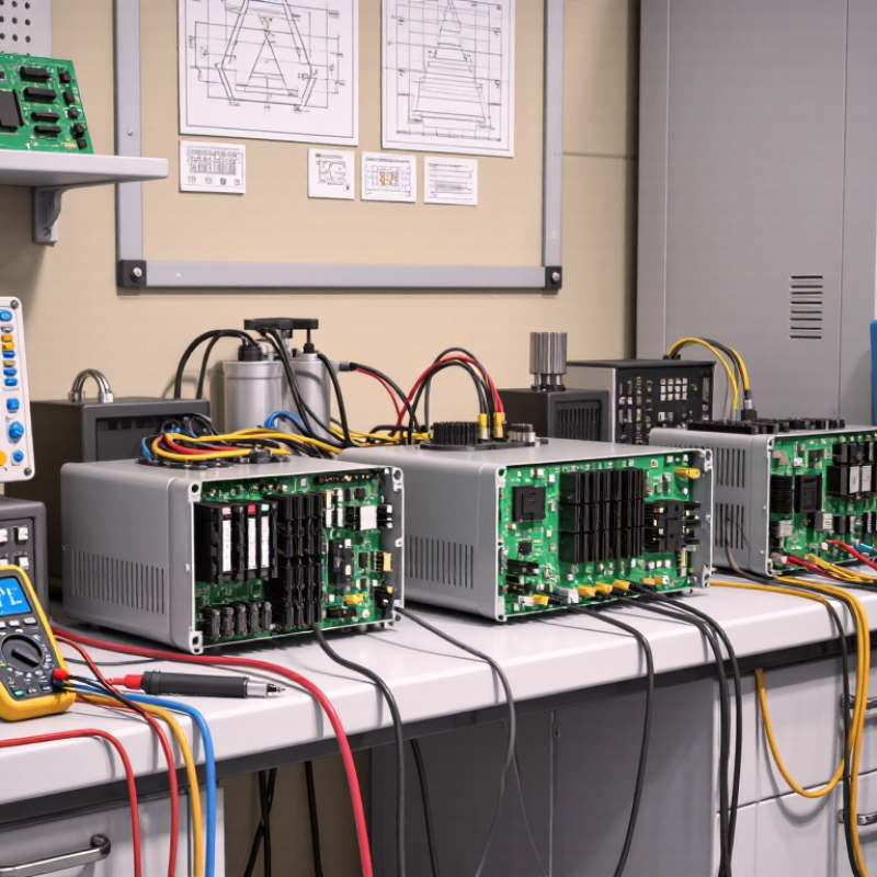
5 Tips to Improve Power Module Control System Compatibility
Define Power Module Control System Compatibility
Power module control system compatibility means more than matching voltage and current ratings. It describes how well the power stage, controller, sensors, firmware, wiring, and protection circuits operate together. A compatible system responds predictably under normal loads, startup conditions, faults, and temperature changes.
Begin by checking electrical interfaces. Confirm signal levels, isolation requirements, grounding methods, and switching frequencies. A control input may accept the correct voltage but still react poorly to noise. Measure it with an oscilloscope during startup and rapid load changes. Small spikes matter.
Communication timing deserves equal attention. Compare command intervals, feedback delays, fault signals, and reset behavior. Two devices can use the same protocol yet disagree about timing. That mismatch may create unstable control. Test communication during brownouts, not only in a quiet laboratory.
Mechanical and thermal details also influence compatibility. Verify connector alignment, mounting pressure, airflow, and heat paths. A module operating near its temperature limit can change switching behavior. Keep temperature sensors close to real hot spots. Remote measurements can look reassuring, but be misleading.
Protection settings must work as a coordinated system. Compare overcurrent thresholds, response times, soft-start limits, and recovery rules. Test one fault at a time. Then test realistic combinations. This is where early assumptions often prove weak. A clean schematic does not guarantee safe behavior.
Finally, document every interface and test result. Include firmware versions, cable lengths, load profiles, and environmental conditions. Repeat tests after revisions. Compatibility is not a permanent label; it is demonstrated performance under defined conditions. Some systems pass the bench test and still need more reflection before deployment.
| Tip | Compatibility Dimension | What It Means | Key Checks | Recommended Design Target | Validation Method |
|---|---|---|---|---|---|
| 1 | Electrical Interface Matching | Ensure that the power module and controller use compatible voltage, current, grounding, and signal conventions. | Confirm control-signal voltage levels, input and output current limits, polarity, isolation requirements, connector pin assignments, and protective-earth arrangements. | Keep every signal within the controller and power-module operating limits, with an engineering safety margin of at least 20% where practical. | Review electrical schematics, perform continuity tests, and measure signal levels under normal and worst-case operating conditions. |
| 2 | Control and Communication Protocols | Make sure command, feedback, diagnostic, and configuration data are exchanged using compatible protocols and data formats. | Check physical-layer requirements, baud rate or link speed, addressing, message identifiers, byte order, scaling factors, timeout behavior, and error handling. | Define a complete interface specification with signal names, units, update rates, valid ranges, default states, and communication-fault responses. | Use protocol analyzers, loopback tests, fault injection, and interoperability tests with representative controllers and loads. |
| 3 | Timing and Dynamic Response | Verify that the power module responds quickly and predictably enough for the control algorithm and application operating cycle. | Measure command latency, feedback delay, sampling interval, switching frequency, startup time, shutdown time, and protection-response time. | Keep the total control-loop delay below the maximum value allowed by the system stability analysis, and document all timing tolerances. | Capture command and feedback waveforms with an oscilloscope or data logger during startup, load changes, braking, and fault conditions. |
| 4 | Thermal and Environmental Compatibility | Confirm that the module, controller, wiring, and enclosure can operate together across the intended temperature, humidity, vibration, and contamination conditions. | Evaluate heat dissipation, airflow, mounting orientation, ambient temperature, altitude, condensation risk, vibration, shock, and enclosure ingress protection. | Maintain the power semiconductor junction and case temperatures below their specified limits, while preserving required electrical clearances and cooling performance. | Perform thermal mapping, temperature-rise testing, environmental chamber testing, vibration testing, and full-load endurance testing. |
| 5 | Functional Safety and Fault Handling | Ensure that the control system and power module enter a defined safe state when faults, abnormal conditions, or communication interruptions occur. | Review overcurrent, overvoltage, undervoltage, overtemperature, short-circuit, loss-of-feedback, watchdog, emergency-stop, and isolation-monitoring behavior. | Define fault thresholds, detection times, reset rules, diagnostic codes, energy-discharge requirements, and safe-state behavior before system integration. | Conduct fault-injection tests, emergency-stop tests, watchdog tests, insulation checks, and verification against the applicable machine or drive safety requirements. |
Load, temperature, and switching frequency can change control behavior. A fixed-frequency method may suit steady loads. Variable-frequency control can respond better at light loads.
Record startup overshoot, recovery time, current ripple, and thermal drift. Test several load levels. A few microseconds may affect fault response.
Keep the loop slower than unstable parasitic effects. It must still respond quickly to real load changes. This balance is not always obvious.
Test current limiting, soft start, and thermal derating together. Use cold starts, rapid load steps, and repeated shutdowns. Separate testing can hide conflicts.
Simulations may miss connector resistance and sensor noise. Test the real assembly, then compare its behavior with the model. The model may be wrong.
Map control signals, grounding, communication paths, voltage ratings, and thermal limits. Cable length and connector resistance can expose hidden instability.
Test startup, shutdown, overload, short interruptions, and communication loss. Record switching noise, response time, current sharing, and fault recovery.
Track temperature, ripple, alarm frequency, firmware changes, and control-loop drift. Set thresholds early. Review data monthly and test alarms quarterly.
Treat unexplained fluctuations as evidence of an incomplete integration model. Revise assumptions instead of forcing the controller to fit. Edge cases still get missed.
Improving power module control system compatibility begins with understanding how the module and controller exchange power, signals, data, and protection commands. Engineers should define compatibility requirements clearly, including voltage and current ranges, timing behavior, signal levels, communication protocols, grounding, and fault responses. Control algorithms must also match the module’s operating characteristics, such as startup behavior, dynamic load response, efficiency limits, and allowable operating ranges.
To enhance compatibility between power modules and control systems, teams should validate performance under realistic thermal conditions, changing loads, startup events, shutdown sequences, and protection scenarios. Testing should confirm stable regulation, accurate fault detection, safe recovery, and reliable communication. After integration, continuous monitoring of temperatures, efficiency, alarms, and operating trends can reveal developing issues before they affect system reliability. A structured process of specification, simulation, testing, and ongoing optimization helps create a more stable, efficient, and maintainable power solution.

 Vdi Medical