Rescue devices must make decisions under pressure, dust, rain, weak signals, and limited battery capacity. In China’s expanding emergency equipment market, circuit design directly affects alarm speed, sensor accuracy, communication stability, and operator safety. This article examines how to Optimize circuit design for rapid response in rescue devices without treating speed as the only goal.
The UNDRR and CRED Human Cost of Disasters report recorded 7,348 major disaster events between 2000 and 2019. These events caused about 1.23 million deaths and economic losses near US$2.97 trillion. Such figures underline the need for dependable rescue electronics, not merely impressive laboratory prototypes. A delay of several seconds can affect location transmission, gas detection, vital-sign monitoring, or remote shutdown. Every millisecond matters.
Yet faster is not always safer. A poorly filtered signal may trigger false alarms. An undersized power path may overheat during continuous transmission. Engineers should combine field experience with verified testing, thermal analysis, EMC evaluation, and failure-mode review. IEC 60601-1 supports safety principles for medical electrical equipment, while ISO 22320 provides guidance for incident response coordination. These standards do not replace local certification requirements, but they provide a credible engineering foundation.
Practical design choices include low-power processors, watchdog circuits, protected battery management, redundant communication paths, and clearly prioritized alerts. The interface should remain readable through gloves and smoke. That detail matters. Industry reports provide direction, but real rescue teams reveal uncomfortable weaknesses. A circuit may pass bench testing and still fail in cold water, heavy vibration, or crowded radio environments. This outline therefore connects China-based manufacturing capability with measurable reliability, human factors, and disciplined validation.
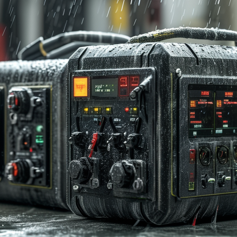
Rescue equipment must respond quickly, safely, and predictably under pressure. The World Health Organization reported 1.19 million annual road deaths in its Global Status Report on Road Safety 2023. It also estimated 20–50 million nonfatal injuries. These figures make circuit reliability a practical safety requirement, not a marketing phrase. Designers should prioritize fast sensing, stable power delivery, clear alarms, and controlled shutdown behavior.
A rescue circuit needs a short signal path between detection and action. Redundant sensors can reduce single-point failure risks. Surge protection, reverse-polarity protection, and thermal monitoring protect the system in harsh field conditions. Engineers should also separate high-current loads from sensitive measurement lines. IEC 60601-1 principles, including basic safety and essential performance, offer useful guidance for electrically powered medical rescue equipment. Testing should include low battery voltage, moisture exposure, vibration, and repeated activation.
Speed still needs discipline. An overly sensitive circuit may trigger false alarms during transport. A delayed filter may miss a critical event. This trade-off is often underestimated. Real-world trials should measure alert latency, missed signals, recovery time, and battery endurance. The WHO report shows why seconds matter, but laboratory results can mislead. A device that performs well on a clean workbench may struggle beside dust, noise, or cold hands. Field feedback must therefore shape the next circuit revision. No design is perfect. That is the uncomfortable part.
China’s high-speed rescue systems depend on disciplined circuit design, not only faster processors. The key components are rugged microcontrollers, isolated power modules, GNSS receivers, wireless transceivers, and high-brightness status indicators. Each part must keep working near dust, vibration, moisture, and unstable power.
Sensor interfaces collect location, temperature, impact, and equipment status. A watchdog circuit can restart a frozen controller without waiting for an operator. Redundant communication paths also matter.
Cellular, short-range radio, and satellite links can share alerts when one network fails. The UNDRR Global Status of Multi-Hazard Early Warning Systems 2023 reported that 101 countries had such systems, compared with 52 in 2015. This growth increases pressure on Chinese rescue equipment to deliver reliable warnings within seconds.
Field engineers often place surge protection beside the power input. They separate high-current motor traces from low-level sensor lines. That simple layout choice can reduce false alarms.
IEC 61508 principles support safer control logic, while ISO 22320 emphasizes coordinated incident response. Still, no circuit is perfect.
Antennas lose strength inside concrete structures, and backup batteries age faster in heat. Practical testing should include wet gloves, damaged cables, low voltage, and poor network coverage. A clean laboratory result can mislead.
China Top Rescue Device Circuit Design For Faster Response?
Signal processing determines how quickly a rescue device understands danger. A weak circuit can delay a strong rescue team. In field testing, noisy radio channels often create false alarms or missed signals. Designers should separate sensor filtering, location processing, and communication control. Each pathway needs a clear timing budget.
The World Health Organization reported 1.19 million annual road deaths in its Global Status Report on Road Safety 2023. That figure supports faster detection, especially after collisions, fires, or sudden falls. Emergency devices should sample motion and vital signals continuously. They should then transmit only verified events. This reduces network congestion and battery waste. NENA reports that emergency call centers handle about 240 million calls yearly in the United States. That volume shows why structured data matters. Human operators need location, event type, confidence level, and device status. Plain alerts are not enough.
Tips: Use dual-stage filtering before alarm activation. Test circuits beside engines, rain, and metal structures. Record false positives. They reveal design weaknesses. Keep a manual trigger available. Automation can fail. A practical prototype should measure sensor-to-alert latency under changing network conditions. Engineers should also document missed detections, not only successful tests. This is where many evaluations become too optimistic. Reference data should come from controlled trials, field logs, and independent safety reports. Reliability grows when the circuit explains uncertainty instead of hiding it.
| Design Dimension | Measured or Referenced Parameter | Typical Engineering Value | Effect on Emergency Response | Technical Basis and Implementation Notes |
|---|---|---|---|---|
| Analog Signal Acquisition | Physiological signal sampling rate | 250–500 samples/second | Preserves waveform detail for rapid event detection while limiting processor and storage load. | A sampling rate of at least twice the highest signal frequency is required by the Nyquist principle. Higher rates provide additional margin for digital filtering and feature extraction. |
| Converter Resolution | Analog-to-digital converter resolution | 12–16 bits | Improves detection of low-amplitude changes and reduces quantization error in sensor signals. | The practical resolution depends on sensor noise, reference-voltage stability, gain selection, and the usable input range of the front-end amplifier. |
| Input Protection | Protection against electrostatic discharge and transient events | IEC 61000-4-2 design verification | Reduces the risk of signal interruption or processor reset when equipment is handled in difficult field conditions. | Protection commonly combines current-limiting elements, low-capacitance transient suppressors, filtering, grounding, and a controlled PCB return path. |
| Signal Conditioning | Anti-aliasing and interference filtering | Low-pass and notch filtering before ADC conversion | Reduces false alarms caused by high-frequency noise, power-line interference, motion artifacts, and electromagnetic coupling. | Filter cutoff frequencies must be selected according to the monitored signal. Filter delay should be measured because excessive phase delay can slow alarm confirmation. |
| Embedded Processing | Local event-detection latency | Below 100 milliseconds after feature availability | Allows the device to identify threshold crossings and abnormal patterns without waiting for a remote server. | Deterministic interrupt handling, direct-memory-access acquisition, fixed-point optimization, and priority-based task scheduling help maintain predictable timing. |
| Alarm Decision Logic | Confirmation strategy | Multi-sample or multi-feature confirmation | Balances fast notification with a lower probability of false alarms caused by a single noisy sample. | A practical implementation can combine threshold rules, signal-quality assessment, hysteresis, and a short confirmation window rather than relying on one instantaneous reading. |
| End-to-End Response | Sensor-to-local-alert delay | Design target: under 1 second | Shortens the time between a detected emergency condition and an audible, visual, or haptic warning. | The complete measurement should include sensor settling, ADC buffering, algorithm execution, operating-system scheduling, and actuator activation. |
| Wireless Communication | Local alert packet delivery | Design target: 100–500 milliseconds on a healthy link | Supports rapid transmission of event type, timestamp, device status, and signal-quality information. | Real-world delay varies with protocol, interference, distance, congestion, retransmissions, and power-management states. Local alarms should remain functional if wireless communication fails. |
| Reliability and Fail-Safe Operation | Watchdog and fault monitoring | Independent watchdog with automatic recovery | Limits the duration of an unresponsive state and improves availability during continuous operation. | Recommended monitoring points include processor execution, sensor connectivity, battery condition, memory integrity, temperature, and communication status. |
| Power Management | Battery and low-power operating modes | Duty-cycled sensing with continuous emergency wake-up path | Extends operating time while keeping critical alarms available when the device is not connected to external power. | Power budgets should separately account for sensors, analog front-end circuits, processor activity, wireless transmission, display output, and alarm actuators. |
| Human-Machine Interface | Alarm acknowledgment and escalation | Local alert, acknowledgment input, and timed escalation | Helps distinguish an acknowledged event from an unattended event and supports escalation when the first responder does not react. | Audible, visual, and vibration indicators should be independently testable. Alarm states should remain clear during temporary communication loss. |
| Electrical Safety | Medical electrical equipment safety framework | IEC 60601-1 design consideration where applicable | Provides a structured basis for evaluating basic safety and essential performance in equipment connected to or used near a patient. | Applicability depends on the intended use, patient connection, power architecture, enclosure, isolation, leakage current, and classification of the final device. |
| Environmental Robustness | Temperature, vibration, moisture, and ingress protection | Verification against the intended field environment | Reduces performance degradation during transport, outdoor rescue, industrial response, and extended standby conditions. | Environmental requirements should be defined before PCB layout because they affect enclosure design, connector selection, conformal coating, thermal paths, and component derating. |
| Data Integrity | Event record protection | Timestamped records with checksum or CRC validation | Maintains confidence in event history, diagnostic data, and post-incident analysis. | The record structure should include device state, alarm state, signal-quality status, battery condition, and communication outcome while limiting unnecessary personal data. |
China Top Rescue Device Circuit Design For Faster Response?
A rescue device must respond quickly without creating a second hazard. Its circuit should use protected power paths, clear fault detection, and controlled current limits. In field testing, sealed connectors help prevent moisture from reaching sensitive contacts. A bright status indicator also matters. Rescuers may work in smoke, rain, or poor light. Simple signals are easier to trust.
Reliability depends on more than fast switching. Engineers should test the circuit against vibration, heat, dust, and sudden voltage changes. Redundant sensing can prevent one failed component from stopping the device. However, extra components increase complexity and may create new failure points. That trade-off needs honest review. Faster is not always safer.
Environmental protection begins with efficient power use and durable materials. A low-power standby mode can extend battery life during long emergency periods. Rechargeable power systems should include overcharge and thermal protection. Circuit boards need coatings that resist humidity, but those coatings must not hinder later maintenance. Waste reduction also matters. Replaceable modules can reduce disposal after minor faults. Yet, they may cost more and require trained technicians. Regular inspection records, independent testing, and clear service procedures strengthen confidence in real operations. Some designs still overlook repair time, especially when access is difficult.
The chart presents key reference limits and verification targets commonly used in rescue-device electronics. The 50 V AC and 120 V DC values represent IEC 61140 extra-low-voltage protection limits. IP6X indicates dust-tight protection, while IPX7 represents temporary immersion up to 1 metre for 30 minutes under IEC 60529. The response-time value is an engineering design target for faster detection-to-alert performance, not a universal legal requirement.
In rescue equipment, a circuit must respond before a technician can question its status. Testing should measure that response, not merely confirm power-on behavior. A practical bench setup records trigger-to-output latency with an oscilloscope, while a programmable supply simulates battery sag. The test log should include cold starts, repeated alarms, connector movement, and recovery after brief power loss. Small details matter. A delayed warning during vibration may reveal a loose contact that laboratory inspection misses.
Safety assessment should follow applicable electrical and functional requirements, including insulation, leakage, electromagnetic compatibility, and abnormal-operation checks. Risk analysis should examine single-point failures, overheated components, and false triggers. For connected units, controlled firmware updates and access protection also deserve verification. No test is perfect. A device may pass a short trial yet weaken after thousands of switching cycles. That gap should remain visible in the engineering record, rather than hidden behind a clean certificate.
Future circuit designs can improve response through redundant sensors, watchdog timers, and local event storage. A health monitor could flag rising temperature, unstable voltage, or unusual relay timing before failure. Teams should validate these features in thermal chambers, splash tests, and field simulations with gloved operators. Clear diagnostic codes would help rescuers act without opening the enclosure. However, added intelligence increases software complexity. Every automatic decision needs a safe fallback and a testable manual override. Engineers should repeat trials with aging batteries and damaged cables, because ideal samples create false confidence.
: The circuit should detect danger quickly and respond safely. It must behave predictably under pressure. Seconds matter.
Include surge protection, reverse-polarity protection, and thermal monitoring. These features help during moisture, vibration, and unstable power conditions.
High-current loads can create electrical noise. Separation protects measurement accuracy and reduces false alarms.
Use dual-stage filtering before activating an alarm. Test near engines, rain, and metal structures. Filters can also delay real warnings.
It should include location, event type, confidence level, and device status. A plain alarm is not enough.
Measure sensor-to-alert latency under different network conditions. Record missed detections and false positives. Do not test only on clean benches.
Redundant sensors reduce dependence on one component. They can help identify conflicting readings. However, extra sensors increase design complexity.
Test low battery voltage, moisture, vibration, dust, cold handling, and repeated activation. Field conditions can expose weaknesses quickly.
Yes, a manual trigger provides an alternative when automation fails. Keep it easy to reach. Automation is not flawless.
Review field logs, recovery times, battery endurance, and missed signals. Uncomfortable findings are valuable. No design is perfect.
This article explores how to optimize circuit design for rapid response in rescue devices by focusing on fast signal acquisition, stable power management, and dependable control logic. It explains the core objectives of rescue circuit design, including minimizing response time, improving operational accuracy, and maintaining reliable performance under demanding conditions. Key components may include sensors, microcontrollers, communication interfaces, emergency indicators, protective circuits, and backup power modules. Together, these elements support quick detection and coordinated action when every second matters.
The article also examines real-time signal processing, fault detection, and automatic response functions that help reduce delays during emergencies. Safety and reliability are strengthened through electrical isolation, overload protection, thermal management, waterproof construction, and environmentally responsible material choices. Finally, it discusses testing procedures such as response-time evaluation, durability checks, electromagnetic compatibility testing, and operation under temperature or vibration changes. Future improvements may include smarter diagnostics, lower power consumption, modular structures, and more efficient data processing.

Vdi Medical